
An Introduction to Hydraulic Model Studies
HYDRAULIC MODELING
The Hydraulic Modeling is generally carried out by various means such as physical hydraulic modeling, electronic/electrical, numerical or mathematical modeling. Physical hydraulic modeling a form of hydraulic modeling, is widely used to investigate hydraulic design and operational issues in hydraulic engineering. The designer and engineers associated with the design, construction and efficient working of the various types of the hydraulic structures such as dams, barrages, bridges, spillways, etc., or hydraulic machines such as turbines, pumps, etc., usually want to know, in advance, how the structures or machines behave after their construction. To clarify such doubts, the hydraulic engineers have to go through an experiment.
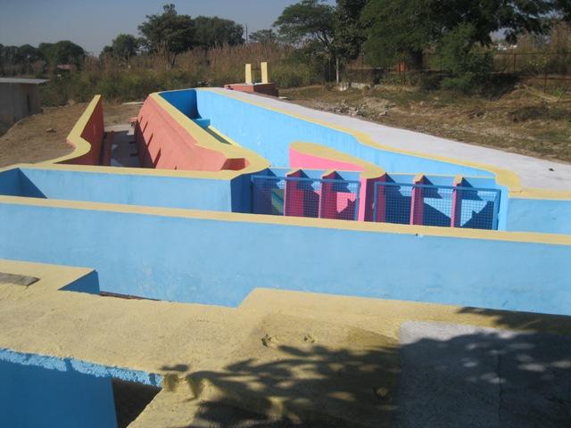
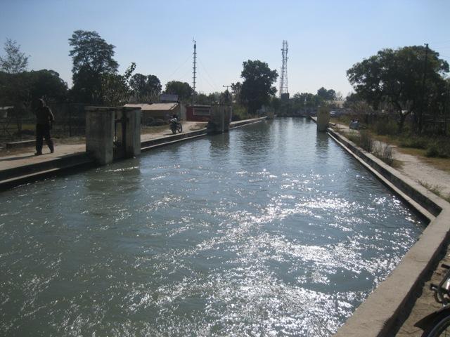
The small scale replica of the actual hydraulic structure/machine is known as ‘model’ and the actual structure / machine is called ‘prototype’ (or simply proto). In wide sense, we can say that a model is a system which converts a given input (geometry, boundary conditions, forces, etc.), into an output (flow rates, levels, pressures, etc.), to be used in hydraulic / civil engineering and operation. Normally, most of the models are of smaller sizes than their corresponding prototypes, but in some cases the models are larger than prototype. Figure shows a prototype and model of a weir. Figure Prototype and Model of a Weir.
Purpose of the Hydraulic Modeling
In Hydraulic Engineering, most of the formulae for the design of hydraulic structures are based on empirical relationships. Many problems of non-uniform and unsteady flow, sediment motion, dispersion, density currents, cases with complicated geometry still defy fully or partially the theoretical approach. Due to the uniqueness of the design and circumstances of different hydraulic structures, lack of experiences exits in this field. Thus, experimental tests on scale models are often the most efficient and sometimes indeed the only method of solving the problem.
History of the Hydraulic Modeling
Exactly who first realized the utility of a hydraulic model is unclear. However, according to the available literature the first concept of simulation of prototype and model scale velocities and forces was proposed by Farninand Reech, a professor of mechanics, School of Marine Engineering, Paris in around 1852. Using this concept of dynamic similarity as proposed by F. Reech, Froude a civil engineer practitioner, proposed the most commonly used non-dimensional number named as Froude number in around 1858. He developed a 250 ft long towing tank for flow resistance studies with small scale hulls and with plank of diverse roughness which began in 1872.
First of all, Obsborne Reynolds introduced an expression for estimating time scale associated with a hydraulic model. In 1885, Reynolds worked with a distorted model (Horizontal Scale 30,000:1 and Vertical Scale 500:1) to investigate some fundamental issues concerning the ship canal between Manchester and liverpool. In 1898, Hubert Engles established the first river hydraulic laboratory at Dresden.
In 1916, a Special Irrigation Cell was established by Bombay Residency to modify irrigation practice to meet agricultural requirement. At present, this laboratory is known as ‘Central Water and Power Research Station (CWPRS), Pune’. In the same year i.e. in 1925, hydraulic laboratories were established in almost all the state of India by the Govt. of India under British Empire to solve the hydraulic problems by a hydraulic model.
HYDRAULIC MODELS AND THEIR SIMILITUDE
A scale-model may be able to reflect the future working of its prototype in all respect completely and fully. In other word we can say that there should be a complete similarity between the prototype and its model. This similarity is known as hydraulic similitude. The model should, therefore, be tested only when we have brought about a complete hydraulic similitude between the prototype and its model.
Types of Similarity
There are three types of similarities exist between model and prototype:
- Geometric Similarity : Geometrical similarity between model and prototype exists when the ratios of all homologous dimensions are equal. This similarity involves the symmetry of the shape.
- Kinematic Similarity : This similarity postulates the similarity of form and motion. This exists if the patterns and paths of the motion of the corresponding particles are geometrically similar and if the ratio of velocities of homologous particles involved in the motion are equal.
- Dynamic Similarity : This is the similarity of mass and forces besides geometric and Kinematic similarity. This exists when the ratios of the homologous forces, which, in any way, affect the motion of homologous particles, are equal.
SIMILITUDE CRITERIA
If two systems (model and prototype) are geometrically, kinematically and dynamically similar, then they are said to be complete similar or completely similitude. For hydraulic model studies, geometric (shape), kinematic (time and velocity), and dynamic (mass and force) similarity should be maintained between model and prototype. However, these ideal conditions are very difficult to achieve in some cases. To overcome these difficulties, we may be satisfied with partial geometrical similarity so as to give complete dynamic similarity which is more essential of the two similarities to be obtained. Because the results obtained from the model tests may be transferred to the prototype by the use of dynamic similarity. The principle of dynamic similarity is based on some model laws.
1. Dominant Force Criteria
(a) Froude’s Law of Similarity
(b) Reynolds’ Law of Similarity
(c) Euler’s Law of Similarity
(d) Mach’s Law of Similarity
(e) Weber’s Law of Similarity
2. Roughness Criteria
3. Tractive Force Theory Criteria
4. Fall Velocity Criteria
5. Equation of Motion Criteria
6. Criteria for Simulation of Air-entraining Vortex Formation on Model
DIFFERENT TYPES OF HYDRAULIC STRUCTURES FOR WHICH MODEL STUDIES ARE TO BE CONDUCTED
- Sedimentation/Desilting chamber/tank
- Spillway, Under sluice and Energy dissipation devices
- Hydraulic Design of Power Intake
- Determination of axes of Barrage, bridge, etc.
- Spillway and Sediment Transport
- Water Quality Studies
- Estimation of High Flood Level
- Studies for flood protective measures
- studies for Canal, Canal Head and Cross Regulators, Cross drainage works (Aquaduct, Super passage, siphon aquaduct, level crossing), etc.
- Sediment Excluder and Sediment Ejector
- Surge Tank and Penstocks
- Diversion Tunnel
- Formation of Vortex in front of power intake/diversion tunnel/HRT, etc.
- Studies of Reservoir sedimentation
- Studies for afflux due to construction of dam/barrage/bridges, etc.
- Studies for guide and afflux bunds due to construction of dam/barrage/bridges, etc.
- Pump Storage Plants
- Calibration of Current meter
- Observations of meteorological parameters (Rainfall, min. & Max.. Temperature, Relative Humidity, Evaporation, soil Temperature, etc.), etc.
OBSERVATIONS TO BE TAKEN IN THE MODEL
Generally the following observations are taken on the model after reproducing the dam/barrage/weir and related structures:
- Discharges passing through the bays/undersluice of spillway/glacis;
- Water levels at different locations and discharge for finding out depth of flow, water surface slope and afflux, etc;
- Velocities at different sections and in bays for determining discharge distribution and concentration of flow including at exit of stilling basin;
- Velocities along structures for assessing the stability;
- Angle of approaching flow to assess the obliquity;
- Surface and bed lines of flow for estimating curvature of flow;
- Erosion (Scour Pattern) on the upstream and downstream of the hydraulic structures;
- Locating areas where sediment deposition or scour may take place;
- Differential head at the piers and divide wall;
- Bed configuration during and after running the hydrograph;
- Afflux in the river due to structures;
- Possibility of formation of vortices in front of power intake, Intakes of HRT, Diversion tunnel, etc.
- Coefficient of discharge for sluice bays, weir bays and head regulator under free flow/critical flow and sub-merged flow conditions;
- Energy dissipation in hydraulic jump under different inflow and tail water conditions and also for different operating condition of gates;
- Performance and hydraulic behaviour of river training works;
- Performance of the basin/plunge pool under oblique approach flow, if any;
- Flushing of sediments deposited vis-a-vis gate operation;
- Negative head/pressure on spillway nappe/weir glacis and at the toe of spillway near energy dissipation arrangement, along pier and abutment, breast wall, HRT/diversion tunnel, etc. wherever required;
- Selection of proper energy dissipation arrangement;
- Profile of undersluice and bays of different hydraulic structures.
- Silt flushing ability of power intake, sedimentation tank, sediment excluder/ejector;
- Determination of dam/barrage/weir vis-à-vis power intake axes; and
- Determination of different flow parameters such as cavitaion index, Froude number, hydraulic gradient/total energy line, flow behaviour in surge tank and at bifurcation of tunnel, upper/lower surge levels in tandem operation, etc.


